Products
SearchCALL NOW336-829-5016

Attachment fitment

MEASURE
THE MACHINE.
BUILD THE FIT.

Illustrated guide sheets for excavator attachments, pin-on thumbs, weld-on thumbs and dozer rakes manufactured by East Attachments.

FITMENT CONFIRMATION

THE MACHINE
SETS THE BUILD.

Machine make and model establish the starting point. Physical dimensions confirm the attachment that will actually fit.

  1. IDENTIFY THE CARRIER

    Provide the machine make, model, operating weight and quick-coupler type when applicable.

  2. VERIFY ACTUAL GEOMETRY

    Record the requested pin, ear, stick or finished-profile dimensions from the machine itself.

  3. SUBMIT A COMPLETE SET

    Pair every requested measurement with clear, straight-on photos of the linkage and measured points.

  4. WAIT FOR SHOP CONFIRMATION

    East Attachments reviews the information before fabrication. Estimated lead time begins only after the required measurements are confirmed.

BEFORE YOU MEASURE

PREPARE THE
MACHINE FIRST.

Small setup errors can create large fitment differences. Work safely, keep the machine stationary and never place yourself beneath unsupported equipment.

  1. IDENTIFY THE CARRIER

    Record the machine make, model, operating weight and the quick-coupler type when applicable.

  2. CLEAN CONTACT POINTS

    Remove dirt and excess grease from pin bores, collars, bushings and ear faces before measuring.

  3. USE THE RIGHT TOOL

    Use calipers for diameters and small fitment details. Use a reliable tape for larger center-to-center distances.

  4. RECORD MILLIMETERS

    Enter excavator pin and fitment measurements in millimeters unless East Attachments requests otherwise.

  5. TAKE CLEAR PHOTOS

    Photograph each measured area straight-on and include a wider view showing the linkage or coupler.

  6. WAIT FOR CONFIRMATION

    Do not assume fabrication has begun until East Attachments confirms the required measurements.

Approved visual guides

SELECT THE
RIGHT DIAGRAM.

Open any guide at full size while measuring. Do not estimate hidden dimensions or substitute measurements from a different machine without confirming them with East Attachments.

GUIDE SHEETS DIRECTORYChoose a guide sheet22 sheets

Excavator Attachment Fitment

Use this guide for standard pin-on excavator attachments. Keep the pin holes visible and measure from the actual machined surfaces.

Example sizing, not a machine-size limit. Any tonnage shown identifies the machine class used for the illustrated model and its dimensions. It does not limit the machine sizes this product can be built for. Contact East Attachments to confirm a build for your machine.

INFORMATION TO RECORD

  • Pin centers between the main pin and power link pin
  • Inside ear width
  • Pin diameters — record main pin and power link pin separately
Translucent CAD excavator attachment fitment guide showing pin centers, inside ear width, and separate main pin and power link pin diameters

Trapezoid Bucket Measurement Guide

Use the translucent isometric bucket view to identify bottom width A, top width B and body height C. Measure body height vertically, excluding mounting ears, rather than along the sloped side. Overall depth is based on excavator weight class. Custom job-specific slopes are possible; call East Attachments at (336) 829-5016 to discuss your project and confirm the required profile before ordering.

Example sizing, not a machine-size limit. Any tonnage shown identifies the machine class used for the illustrated model and its dimensions. It does not limit the machine sizes this product can be built for. Contact East Attachments to confirm a build for your machine.

PROFILE MEASUREMENTS & ORDERING DETAILS

  • Record bottom width A, top width B and body height C using consistent units.
  • Provide the machine make and model, operating weight, and coupler type or direct pin-on arrangement.
  • Use the Excavator Attachment Fitment guide for pin centers, inside ear width and pin diameters when applicable.
  • Describe the required trench or ditch profile, material and application; specify your tooth preference and confirm overall depth.
  • Call East Attachments before ordering to discuss any custom job-specific slope.
Translucent isometric trapezoid bucket with highlighted bottom width A, top width B and body height C, measurement recording fields, machine and hookup details, and custom-slope phone consultation guidance

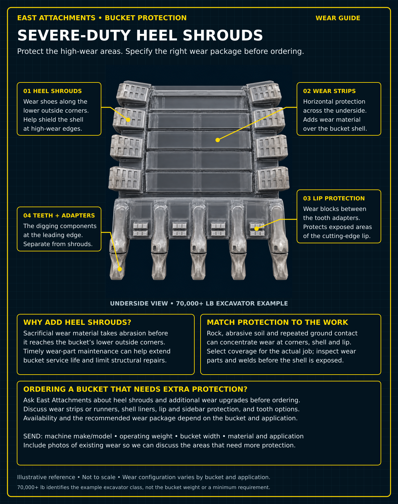
Severe-Duty Heel Shrouds & Bucket Wear Protection

Identify heel shrouds along the bucket’s lower outside corners, underside wear strips, lip protection between tooth adapters, and the teeth and adapters. Sacrificial wear material helps protect the bucket shell from abrasion; timely wear-part maintenance can help extend service life and limit structural repairs. The illustrated bucket is an example for a 70,000+ lb excavator, not a bucket-weight specification.

Example sizing, not a machine-size limit. Any tonnage shown identifies the machine class used for the illustrated model and its dimensions. It does not limit the machine sizes this product can be built for. Contact East Attachments to confirm a build for your machine.

WEAR PROTECTION & ORDERING DETAILS

  • Ask about heel shrouds and additional wear upgrades before ordering a bucket that needs extra protection.
  • Discuss wear strips or runners, shell liners, lip and sidebar protection, and tooth options; recommendations and availability depend on the bucket and application.
  • Provide machine make and model, operating weight, bucket width, material and intended application.
  • Include photos of existing wear to help identify the areas that need additional protection.
Translucent CAD underside view of an excavator bucket identifying severe-duty heel shrouds, horizontal wear strips, cutting-edge lip protection, and teeth with adapters, with benefits and wear-upgrade ordering guidance

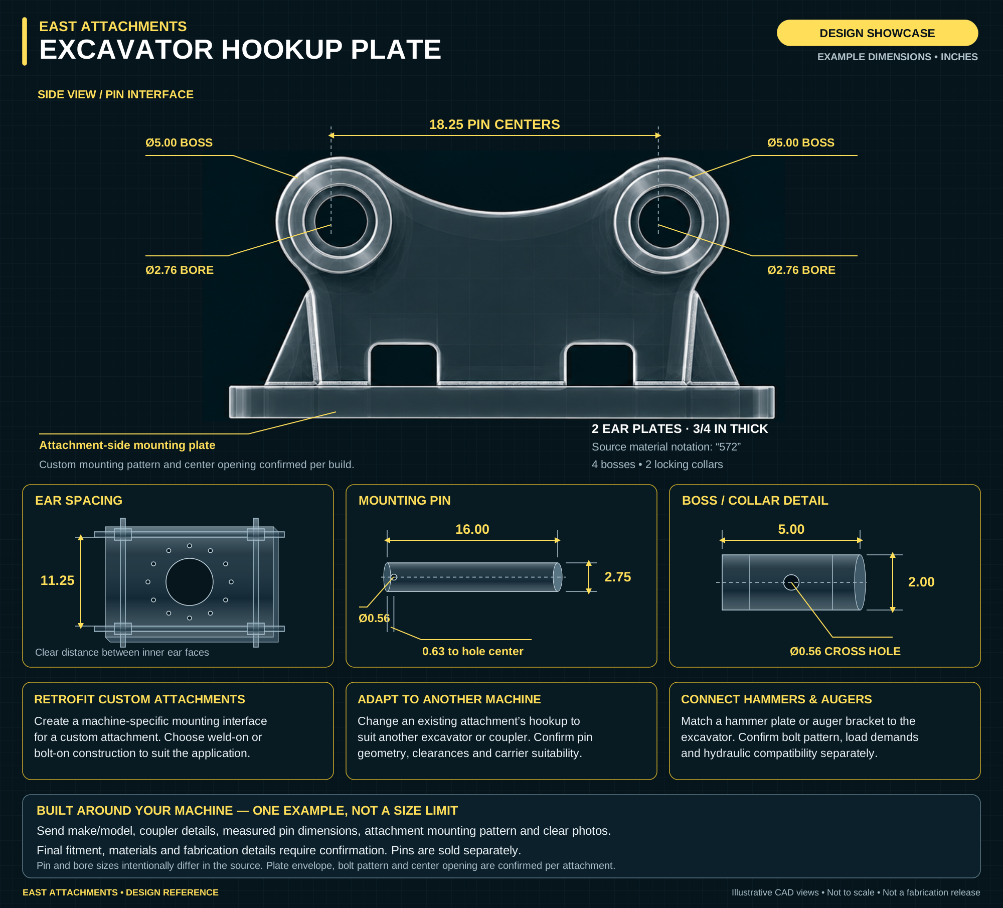
Excavator Hookup Plate Design Showcase

Explore a machine-specific hookup mounting plate for retrofitting custom attachments, changing an existing attachment to suit another excavator, or adapting a hammer plate or auger bracket. This example shows paired mounting ears, machined bosses, reinforcing gussets and an attachment-side mounting plate. Weld-on and bolt-on configurations are available. The illustrated dimensions describe one build and do not establish compatibility with another machine. Pins are sold separately.

Example sizing, not a machine-size limit. Any tonnage shown identifies the machine class used for the illustrated model and its dimensions. It does not limit the machine sizes this product can be built for. Contact East Attachments to confirm a build for your machine.

EXAMPLE DIMENSIONS & INQUIRY DETAILS

  • Example mounting geometry: 18.25 in pin centers; 11.25 in clear ear spacing; Ø5.00 in bosses and Ø2.76 in bores at both ends.
  • Example pin: 16.00 in long × 2.75 in diameter; Ø0.56 in cross hole with its center 0.63 in from the end.
  • Boss/collar detail: 5.00 × 2.00 in with Ø0.56 in hole. Source specifies 4 bosses, 2 locking collars and 2 ear plates, 3/4 in thick, marked ‘572’.
  • Before inquiry: current attachment, new excavator make/model, coupler details, pin diameters, pin centers, inside ear spacing and weld-on or bolt-on preference.
  • For hammer plates and augers: provide the mounting pattern, attachment specifications and hydraulic requirements. The plate adapts the mechanical interface; hydraulic compatibility and structural suitability must be confirmed separately.
CAD excavator hookup plate showcase with an enlarged CAD side view, plan view and component details, 18.25-inch pin centers, 11.25-inch inner ear spacing, 5.00-inch boss diameters, 2.76-inch bores, 16.00 by 2.75-inch pin detail, 0.63-inch retention-hole offset, 0.56-inch cross holes, 5.00 by 2.00-inch boss and collar detail, and three-quarter-inch ear plates

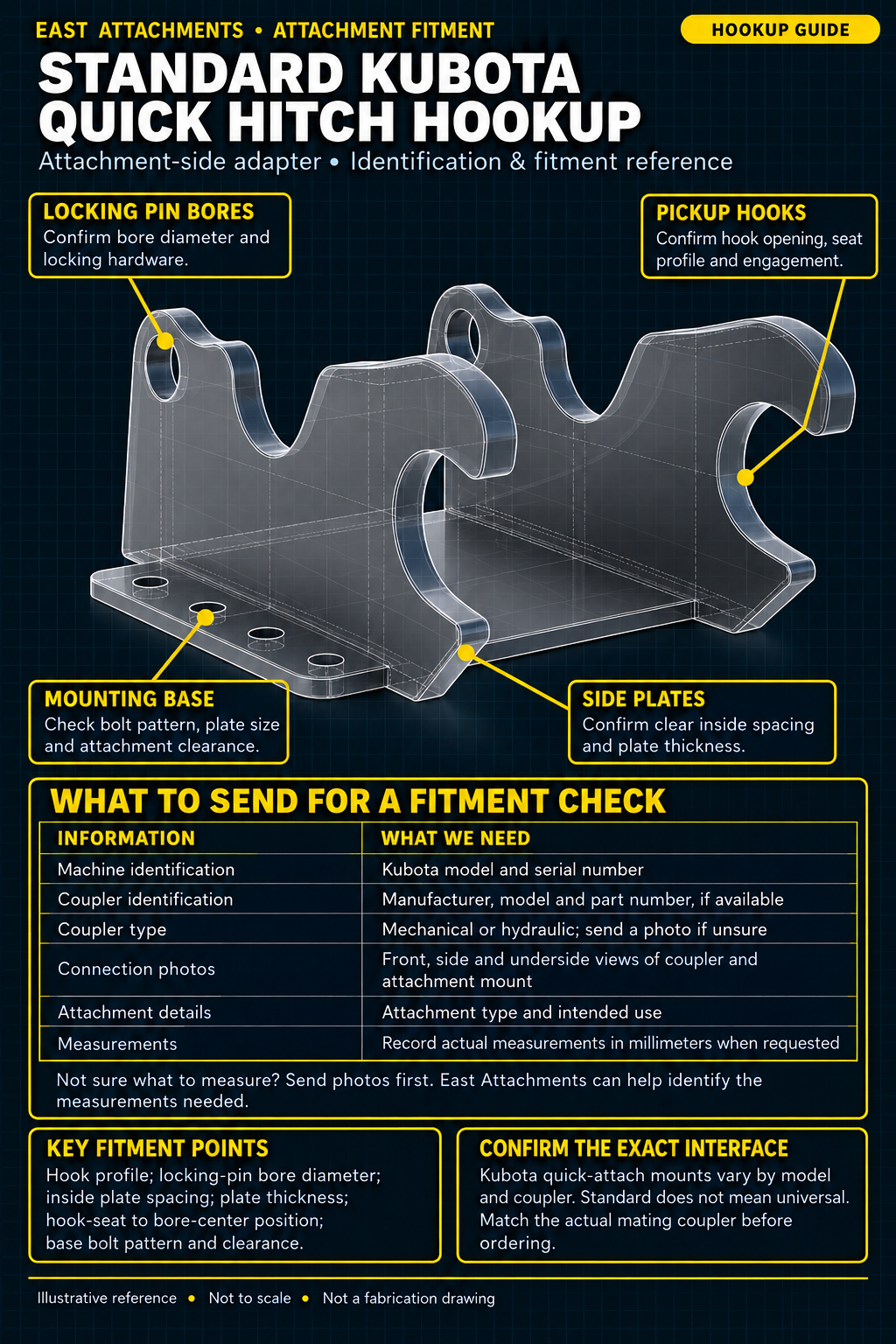
Standard Kubota Quick Hitch Hookup Guide

Identify the attachment-side Kubota-style quick hitch adapter with a translucent CAD illustration of its locking pin bores, pickup hooks, mounting base and side plates. Mounts vary by machine model and coupler; standard does not mean universal. Confirm the actual mating interface before ordering.

WHAT TO SEND FOR A FITMENT CHECK

  • Send the Kubota machine model and serial number, plus the coupler manufacturer, model and part number if available.
  • Identify mechanical or hydraulic operation; provide clear front, side and underside photos of the coupler and existing attachment mount.
  • Provide the attachment type and intended use. Record actual measurements in millimeters when requested.
  • Confirm hook profile, locking-pin bore diameter, inside plate spacing, plate thickness, hook-seat to bore-center position, base bolt pattern and clearance against the actual mating coupler.
Translucent CAD Kubota-style quick hitch adapter with locking pin bore, pickup hook, mounting base and side plate callouts, plus a customer fitment checklist

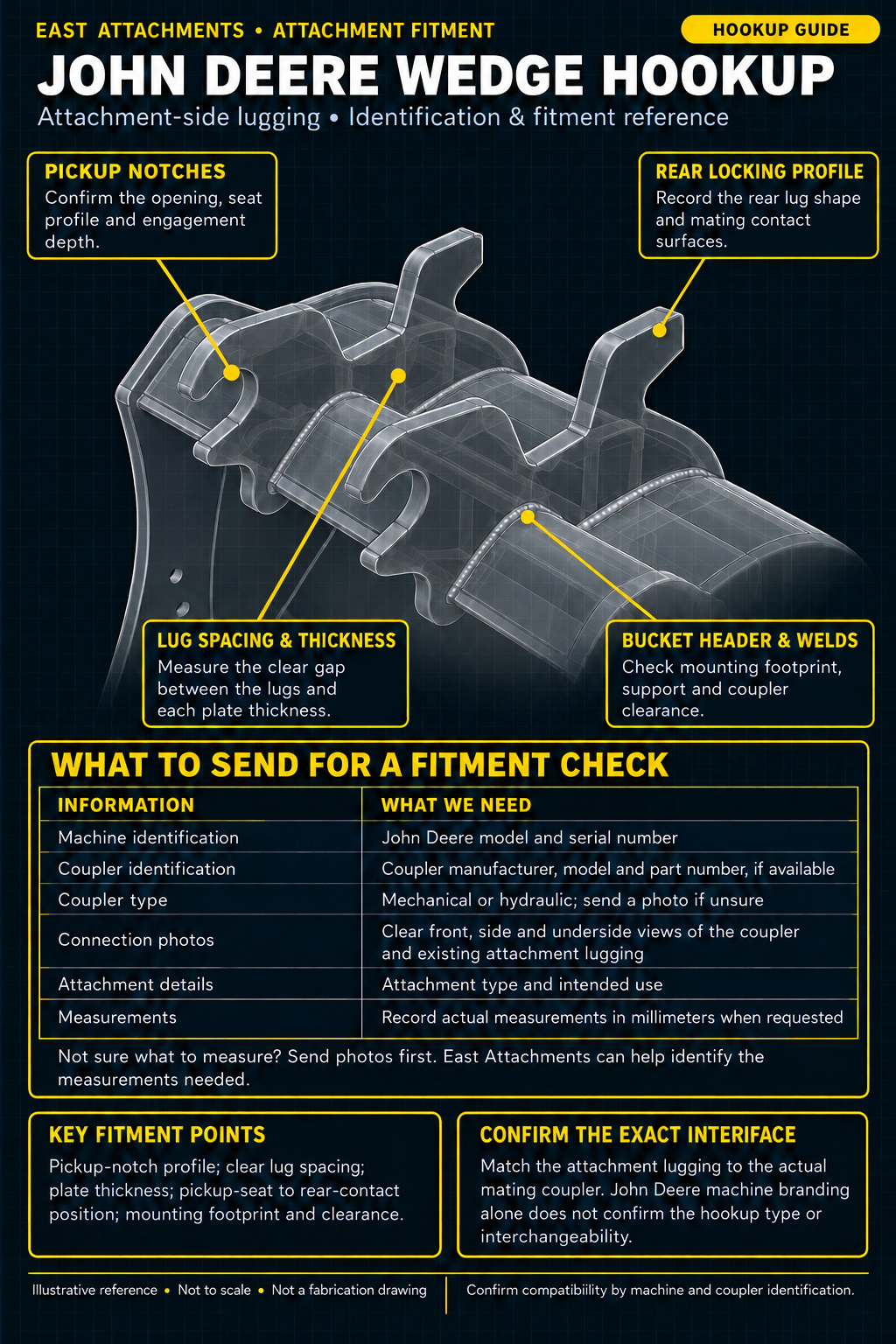
John Deere Wedge Hookup Guide

Identify the attachment-side lugging shown in this John Deere wedge-style hookup guide. The translucent CAD illustration highlights pickup notches, rear locking profiles, lug spacing and the bucket header. Confirm the actual mating coupler rather than relying on machine branding or generic dimensions.

WHAT TO SEND FOR A FITMENT CHECK

  • Send the John Deere machine model and serial number, plus the coupler manufacturer, model and part number if available.
  • Identify mechanical or hydraulic operation; provide clear front, side and underside photos of the coupler and existing attachment lugging.
  • Provide the attachment type and intended use. Record actual measurements in millimeters when requested.
  • Confirm pickup-notch profile, clear lug spacing, plate thickness, pickup-seat to rear-contact position, mounting footprint and clearance against the actual mating coupler.
Translucent CAD John Deere wedge-style attachment lugging with pickup notch, rear locking profile, lug spacing and bucket header weld callouts, plus a customer fitment checklist

TAG / Wain-Roy Style Hookup Guide

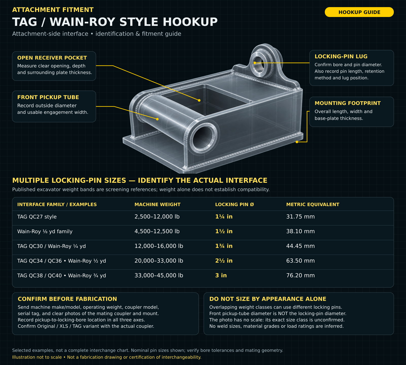
Identify an attachment-side TAG / Wain-Roy style hookup using the front pickup tube, open receiver pocket, locking-pin lug and mounting footprint. The translucent CAD illustration shows the hookup only. Published excavator weight bands help narrow the interface family, but overlapping ranges mean machine weight alone does not establish compatibility.

IDENTIFY & MEASURE THE INTERFACE

  • Identify the coupler make, model, serial tag and Original, XLS or TAG variant; provide machine make/model, operating weight and mating-interface photos.
  • Measure the front pickup tube outside diameter and engagement width, receiver opening and depth, plate thicknesses, and mounting footprint.
  • Confirm locking-pin diameter, bore, pin length, retention method and pickup-to-locking-bore position. The pickup tube is not the locking pin.
  • Reference locking-pin diameters include 1¼, 1½, 1¾, 2½ and 3 inches. Confirm the actual coupler and mating geometry before fabrication; the photographed size class is unconfirmed.
Translucent CAD TAG Wain-Roy style hookup with front pickup tube, open receiver pocket, locking-pin lug and mounting footprint callouts, plus five nominal locking-pin sizes and reference excavator weight ranges

Bobcat Quick X-Change Hookup Guide

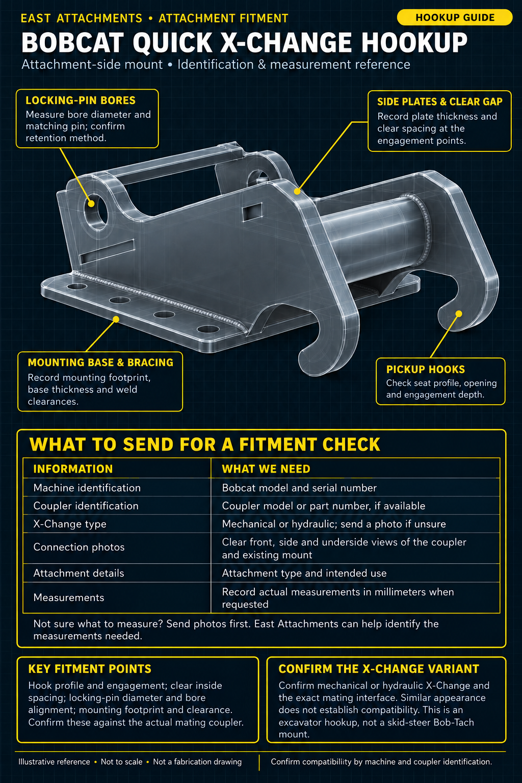
Identify an attachment-side X-Change style mount using its pickup hooks, locking-pin bores, side plates and mounting base. This translucent CAD guide explains what to send for a fitment check without relying on generic example dimensions. Confirm the exact machine and mating coupler before fabrication.

WHAT TO SEND FOR A FITMENT CHECK

  • Send the Bobcat machine model and serial number, plus the coupler model or part number if available.
  • Identify mechanical or hydraulic X-Change; send clear front, side and underside photos of the coupler and existing mount if unsure.
  • Provide the attachment type and intended use. Record actual measurements in millimeters when requested.
  • Confirm hook profile and engagement, clear inside spacing, locking-pin diameter and bore alignment, mounting footprint and clearance against the actual mating coupler.
Translucent CAD Bobcat Quick X-Change attachment-side mount with pickup hook, locking-pin bore, side plate and mounting base callouts, plus a customer fitment checklist

How Our Coupler Works

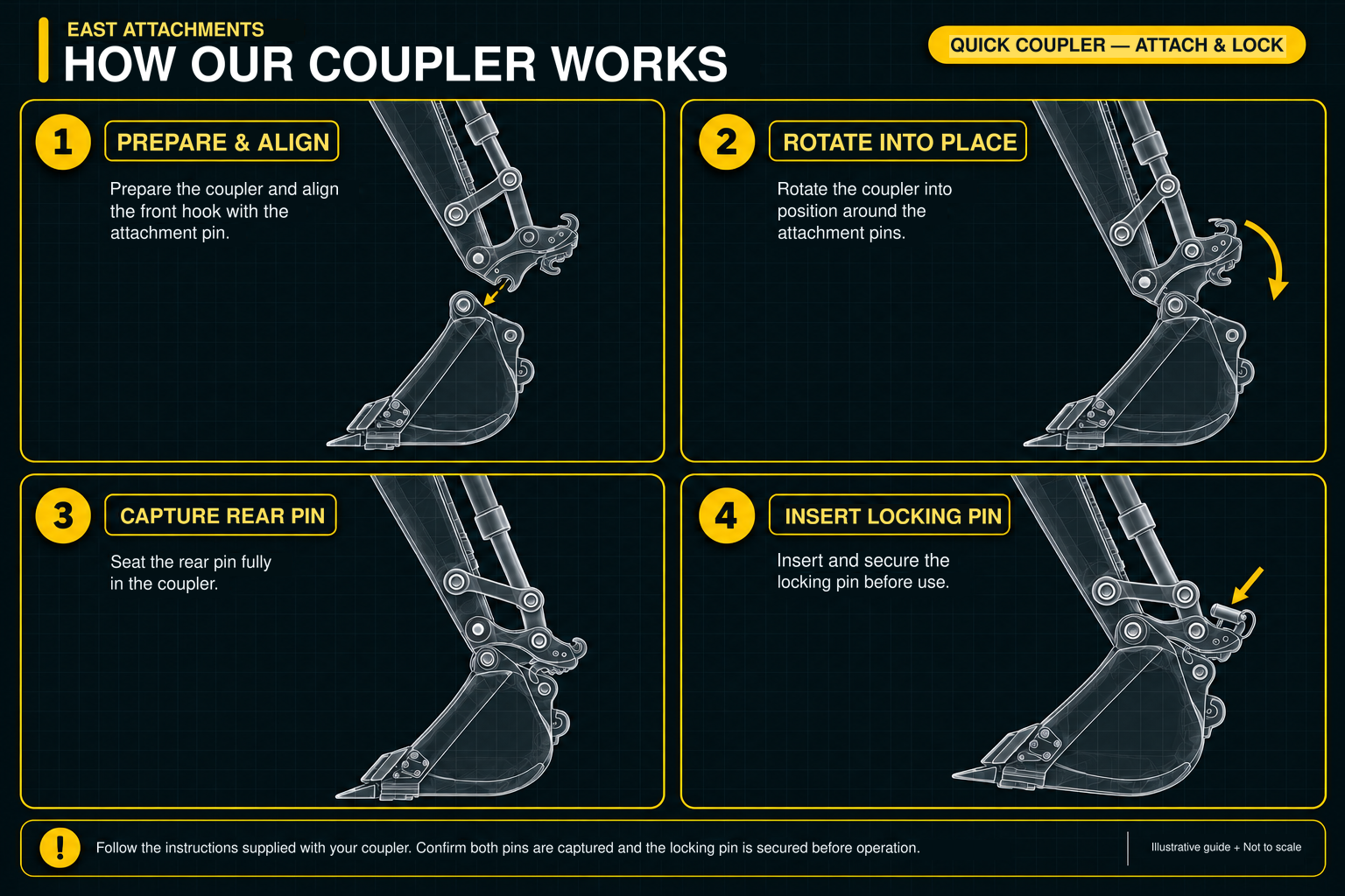
A four-step illustrated overview of attaching and locking the manual quick coupler. Follow the instructions supplied with your coupler and confirm both attachment pins are captured and the locking pin is secured before operation.

Hydraulic hoses and hydraulic lines are not included in orders for hydraulic configurations.

Example sizing, not a machine-size limit. Any tonnage shown identifies the machine class used for the illustrated model and its dimensions. It does not limit the machine sizes this product can be built for. Contact East Attachments to confirm a build for your machine.

ATTACH & LOCK

  • Prepare and align
  • Rotate into place
  • Capture rear pin
  • Insert and secure the locking pin
Semi-transparent CAD guide showing prepare and align, rotate into place, capture the rear pin, and insert the locking pin with the coupler fully seated on the bucket.

Pin-On Thumb Measurements

A pin-on thumb requires detailed bucket, stick, collar and pin information so the thumb and required extended-length pin can be built around the machine.

Hydraulic hoses and hydraulic lines are not included in orders for hydraulic configurations.

Example sizing, not a machine-size limit. Any tonnage shown identifies the machine class used for the illustrated model and its dimensions. It does not limit the machine sizes this product can be built for. Contact East Attachments to confirm a build for your machine.

INFORMATION TO RECORD

  • Cross hole diameter and cross hole position
  • Locking collar width and outside-to-outside of bushings
  • Pin diameter and whether the pin is grease-able
  • Center of pin to stick face and top of bucket
  • Center of pin to teeth tip
  • Edge of stick to end of link assembly and stick width
  • Bucket width and number of teeth
Detailed East Attachments pin-on thumb measurement guide with bucket, stick, pin and collar dimensions

Pin-On Thumb Assembly & Alignment

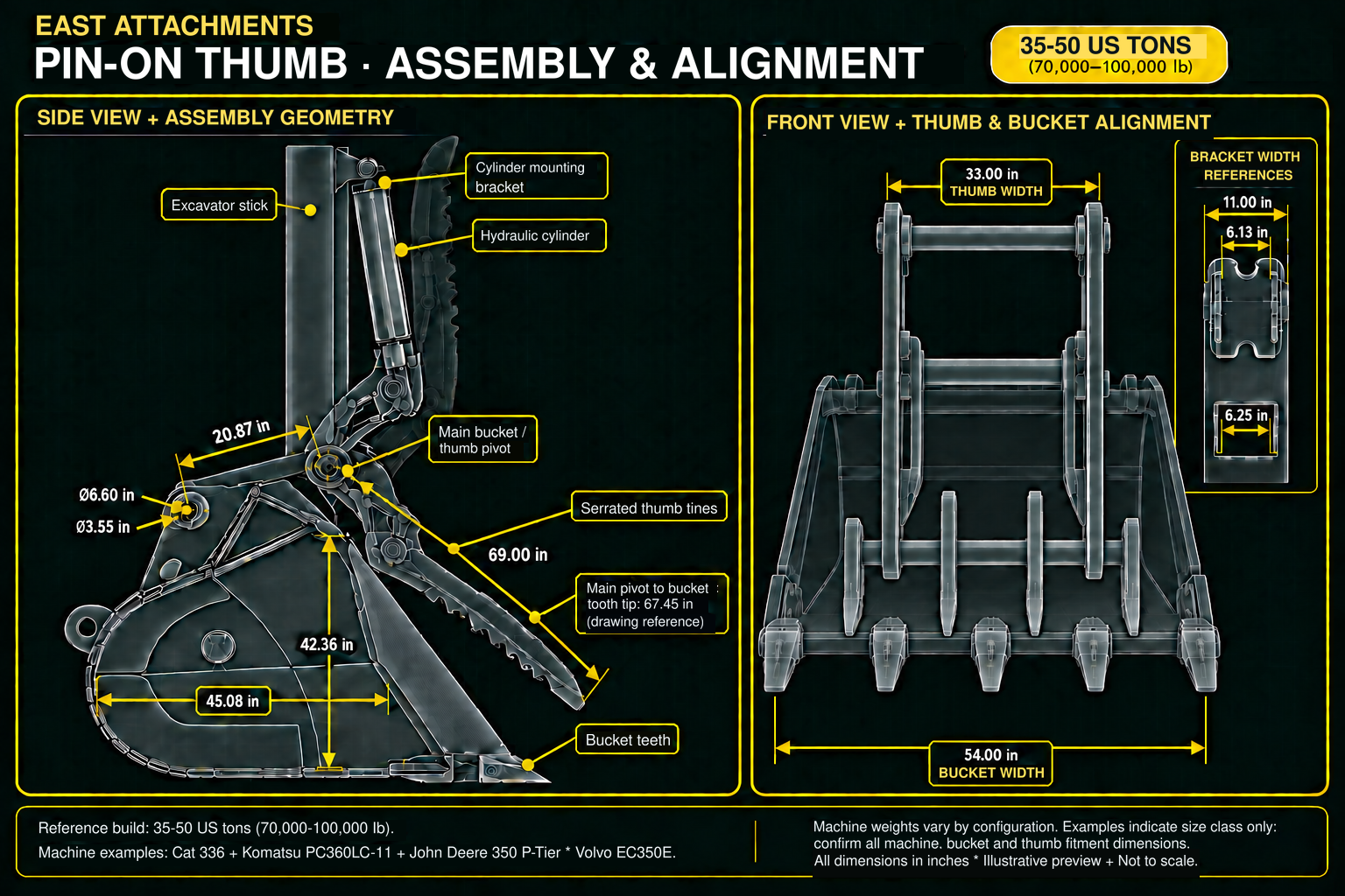
Reference assembly and bucket-to-thumb alignment for a 35–50 US ton (70,000–100,000 lb) machine and 54-inch bucket. Machine examples include Cat 336, Komatsu PC360LC-11, John Deere 350 P-Tier and Volvo EC350E. These indicate size class only; weights vary by configuration and all fitment must be confirmed.

Hydraulic hoses and hydraulic lines are not included in orders for hydraulic configurations.

Example sizing, not a machine-size limit. Any tonnage shown identifies the machine class used for the illustrated model and its dimensions. It does not limit the machine sizes this product can be built for. Contact East Attachments to confirm a build for your machine.

ASSEMBLY & ALIGNMENT REFERENCES

  • 54-inch bucket and 33-inch thumb reference widths
  • Side-view pivot, bucket and bracket reference dimensions
Semi-transparent CAD pin-on thumb assembly with a raised position around the main pivot, and front view showing four thumb tines between five bucket teeth

Pin-On Thumb Component Details

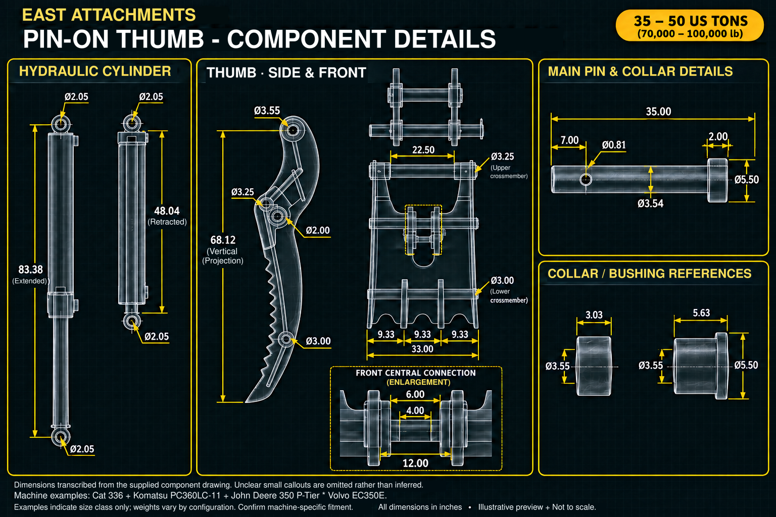
Companion component sheet for the illustrated 35–50 US ton pin-on thumb build. Review the hydraulic cylinder, thumb, main pin and collar details alongside the assembly sheet. Reference dimensions are not universal specifications; confirm the machine-specific build with East Attachments.

Hydraulic hoses and hydraulic lines are not included in orders for hydraulic configurations.

Example sizing, not a machine-size limit. Any tonnage shown identifies the machine class used for the illustrated model and its dimensions. It does not limit the machine sizes this product can be built for. Contact East Attachments to confirm a build for your machine.

COMPONENT REFERENCES

  • Hydraulic cylinder extended and retracted reference lengths
  • Thumb side profile, front spacing and connection details
  • Main pin and collar reference dimensions
CAD pin-on thumb component sheet showing extended and retracted hydraulic cylinder, thumb side and front views, main pin, collars and central connection detail

Weld-On Thumb Selection

Use this guide for weld-on manual and weld-on hydraulic thumbs. Position the bucket teeth at 90 degrees from the stick before taking Dimension 1.

Hydraulic hoses and hydraulic lines are not included in orders for hydraulic configurations.

Example sizing, not a machine-size limit. Any tonnage shown identifies the machine class used for the illustrated model and its dimensions. It does not limit the machine sizes this product can be built for. Contact East Attachments to confirm a build for your machine.

INFORMATION TO RECORD

  • Dimension 1: distance from the stick to the bucket tooth
  • Dimension 2: flat width of the stick, excluding sides and weld
  • Note plates, obstructions or non-flat areas welded to the measured side
East Attachments weld-on excavator thumb selection guide showing stick-to-tooth distance and flat stick width

Weld-On Thumb Installation

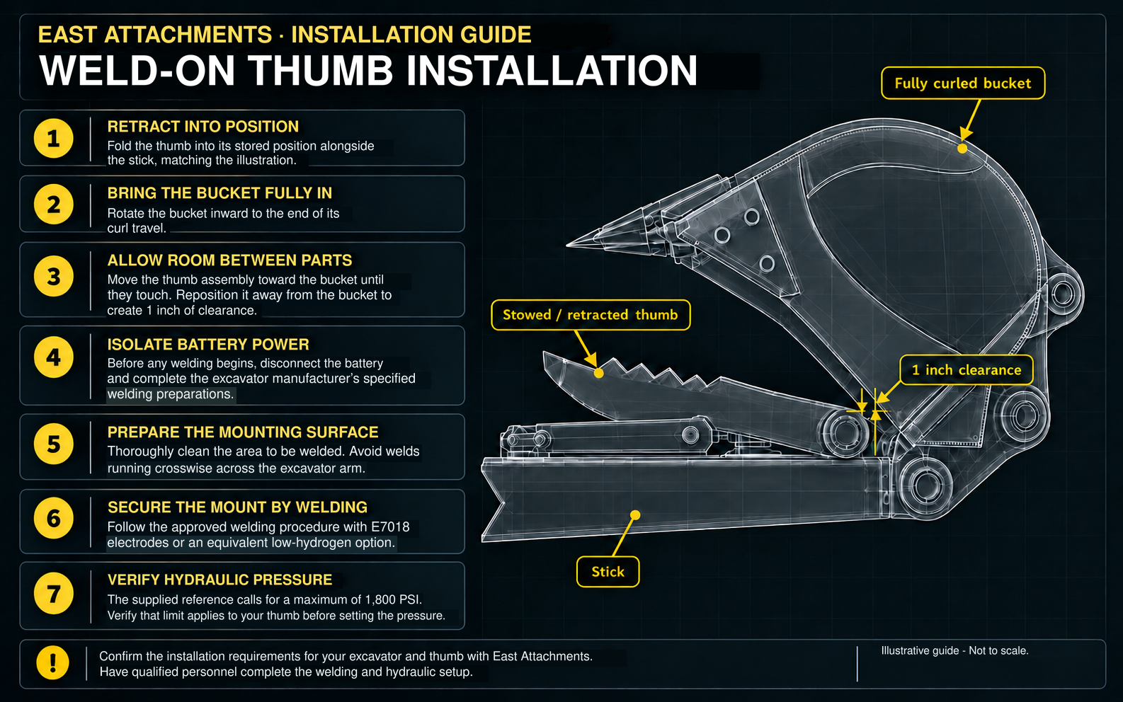
Companion installation reference for weld-on thumbs, showing the stowed thumb, fully curled bucket and 1-inch clearance. Confirm the requirements for your excavator and thumb with East Attachments; qualified personnel should complete welding and hydraulic setup.

Hydraulic hoses and hydraulic lines are not included in orders for hydraulic configurations.

Example sizing, not a machine-size limit. Any tonnage shown identifies the machine class used for the illustrated model and its dimensions. It does not limit the machine sizes this product can be built for. Contact East Attachments to confirm a build for your machine.

INSTALLATION OVERVIEW

  • Retract the thumb, curl the bucket fully inward and establish clearance
  • Prepare battery isolation and mounting surfaces before welding
  • Follow the approved welding procedure and verify thumb-specific hydraulic pressure requirements
Semi-transparent CAD weld-on thumb installation guide with seven steps, a stowed thumb beside the stick, fully curled bucket and 1-inch clearance callout

How to Measure Your Dozer Blade

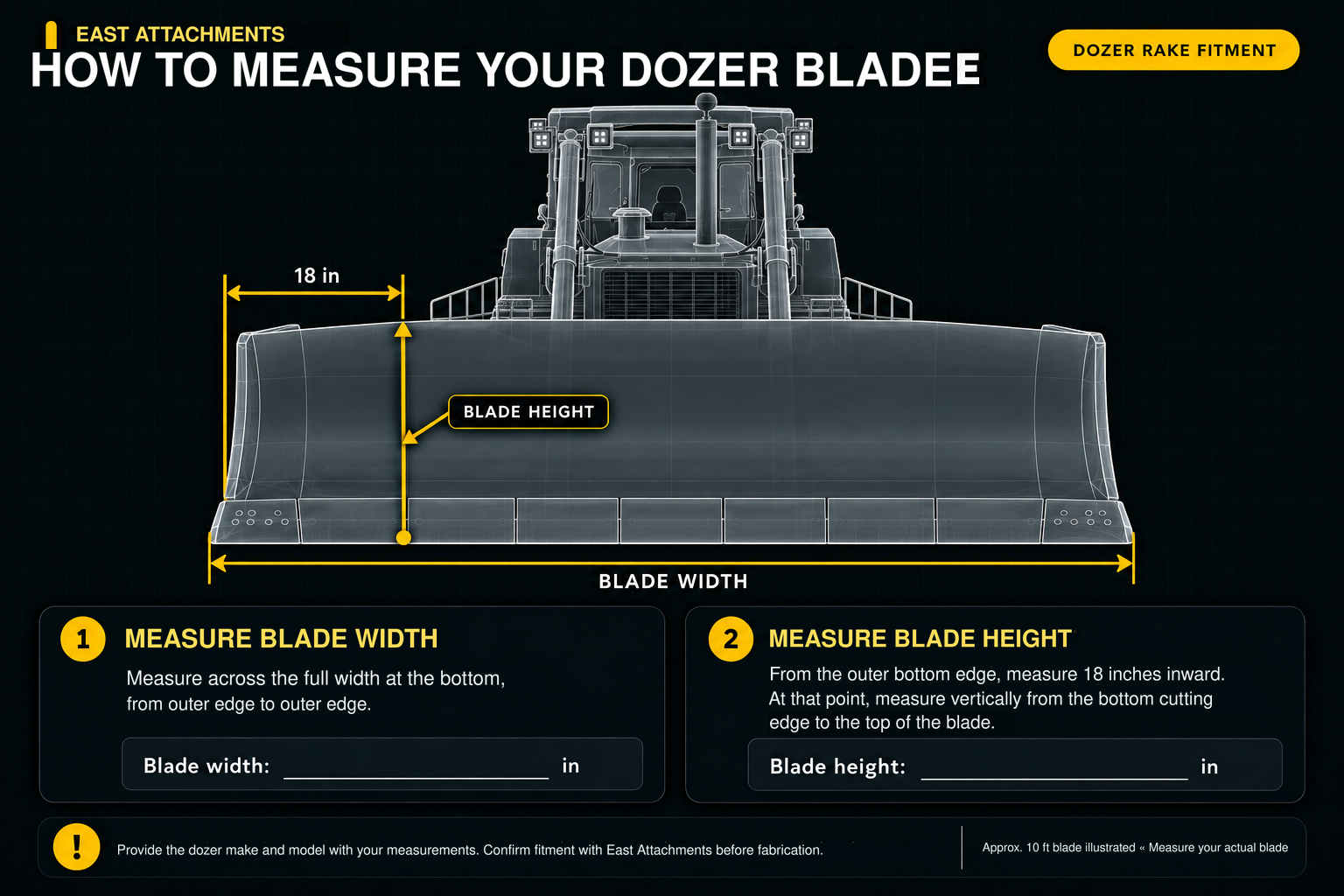
Measure the full blade width at the bottom, from outer edge to outer edge. For blade height, measure 18 inches inward from the outer bottom edge, then measure vertically from the bottom cutting edge to the top of the blade. Supply the dozer make and model with your measurements.

Example sizing, not a machine-size limit. Any tonnage shown identifies the machine class used for the illustrated model and its dimensions. It does not limit the machine sizes this product can be built for. Contact East Attachments to confirm a build for your machine.

MEASURE & RECORD

  • Full blade width at the bottom
  • Blade height measured 18 inches inward from the outer bottom edge
  • Dozer make and model; confirm fitment before fabrication
Front-facing translucent CAD dozer with cab and hydraulic details behind an approximately 10-foot example blade, showing full bottom-edge width and blade height measured 18 inches inward from the outer bottom edge

Dozer Rake Measurement Guide

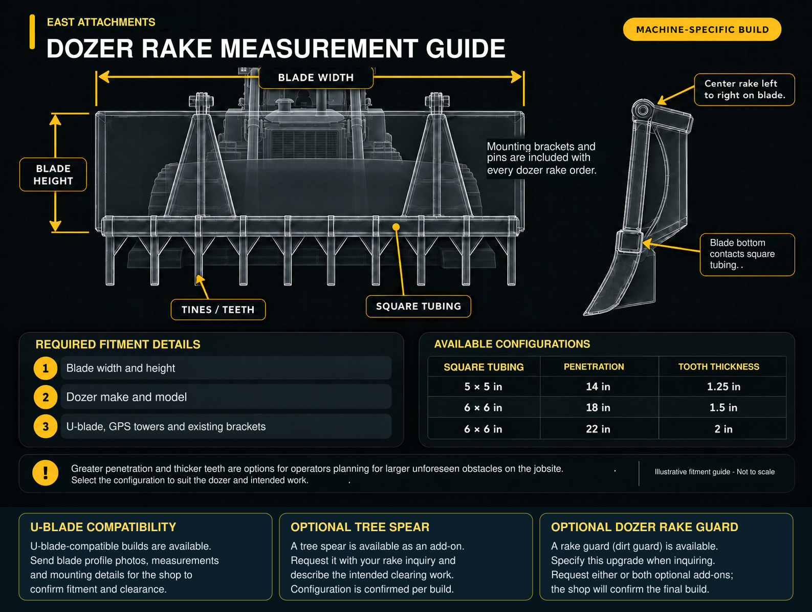
Record the blade width and height, dozer make and model, and any U-blade, GPS towers or existing brackets. Mounting brackets and pins are included with every dozer rake order. Greater penetration and thicker teeth are options for operators planning for larger unforeseen obstacles on the jobsite. Select the configuration to suit the dozer and intended work. U-blade-compatible builds are available with machine-specific fitment confirmation. Optional tree spear and dozer rake guard upgrades are available; request either or both with your inquiry.

Example sizing, not a machine-size limit. Any tonnage shown identifies the machine class used for the illustrated model and its dimensions. It does not limit the machine sizes this product can be built for. Contact East Attachments to confirm a build for your machine.

AVAILABLE CONFIGURATIONS

  • 5 × 5-inch square tubing — 14-inch penetration — 1.25-inch teeth
  • 6 × 6-inch square tubing — 18-inch penetration — 1.5-inch teeth
  • 6 × 6-inch square tubing — 22-inch penetration — 2-inch teeth
  • U-blade-compatible builds: provide blade profile photos, measurements and mounting details for confirmation
  • Optional tree spear and optional dozer rake guard (dirt guard); specify either or both
CAD-style dozer rake guide with cab and dozer details behind the front-view rake, showing blade width and height, tines and square tubing, with three configuration combinations, included mounting brackets and pins, U-blade compatibility, optional tree spear and optional dozer rake guard

Wheel Loader Attachment Measurement Guide

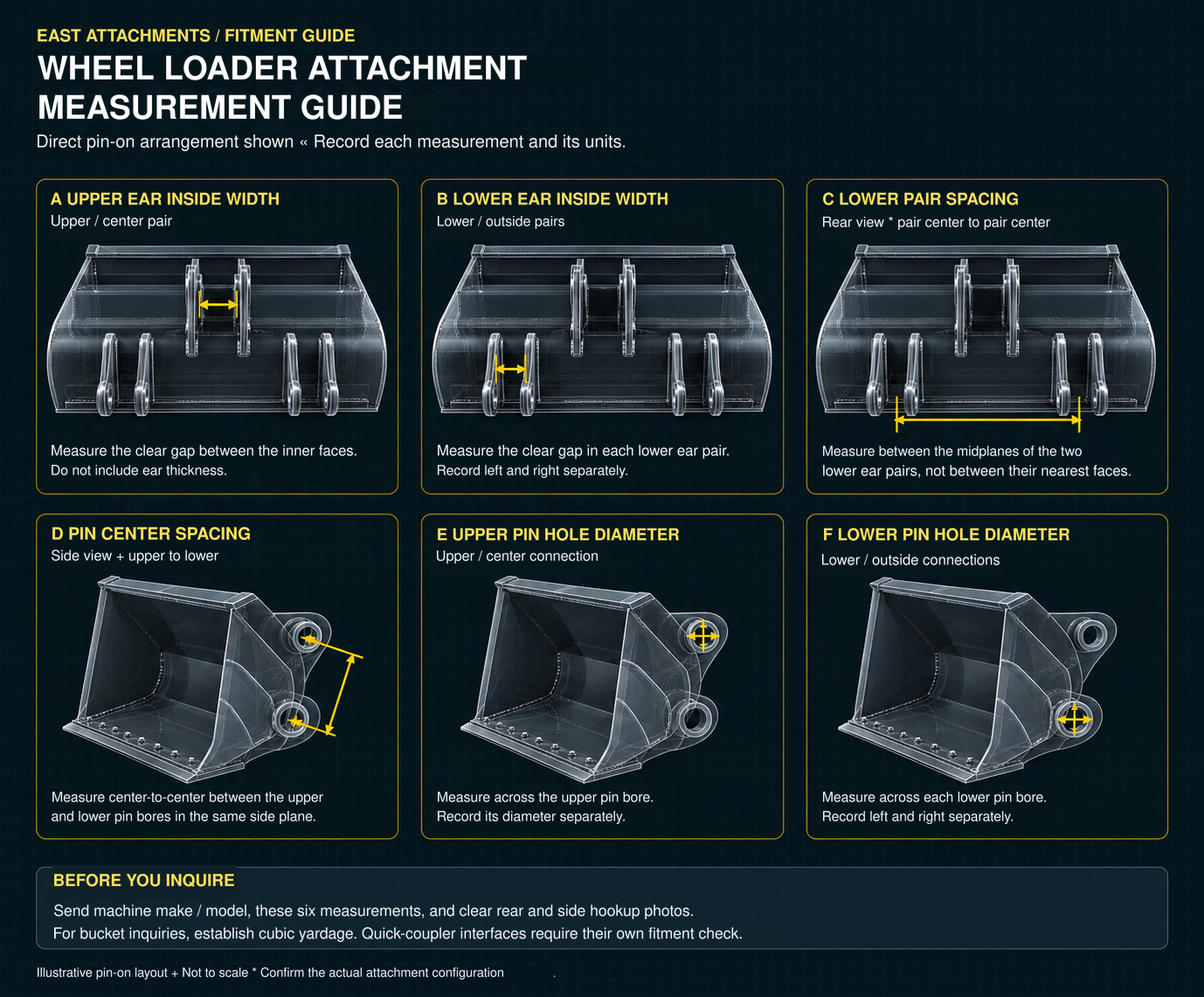
Record the six hookup measurements for the illustrated direct pin-on arrangement. Provide your loader make and model, measurement units, and clear rear and side hookup photos. Measure the actual attachment configuration; quick-coupler interfaces require a separate fitment check. Establish cubic yardage before inquiring about a bucket.

Example sizing, not a machine-size limit. Any tonnage shown identifies the machine class used for the illustrated model and its dimensions. It does not limit the machine sizes this product can be built for. Contact East Attachments to confirm a build for your machine.

MEASUREMENTS TO PROVIDE

  • Upper / center ear pair — clear inside width
  • Lower / outside ear pairs — clear inside width, left and right separately
  • Lower ear-pair spacing — pair center to pair center
  • Upper-to-lower pin bore spacing — center to center
  • Upper / center pin hole — diameter
  • Lower / outside pin holes — diameters, left and right separately
Detailed translucent CAD wheel loader bucket rear and side views showing upper and lower inside ear widths, lower ear-pair spacing, upper-to-lower pin centers, and upper and lower pin-hole diameters

Wheel Loader Bucket Guide

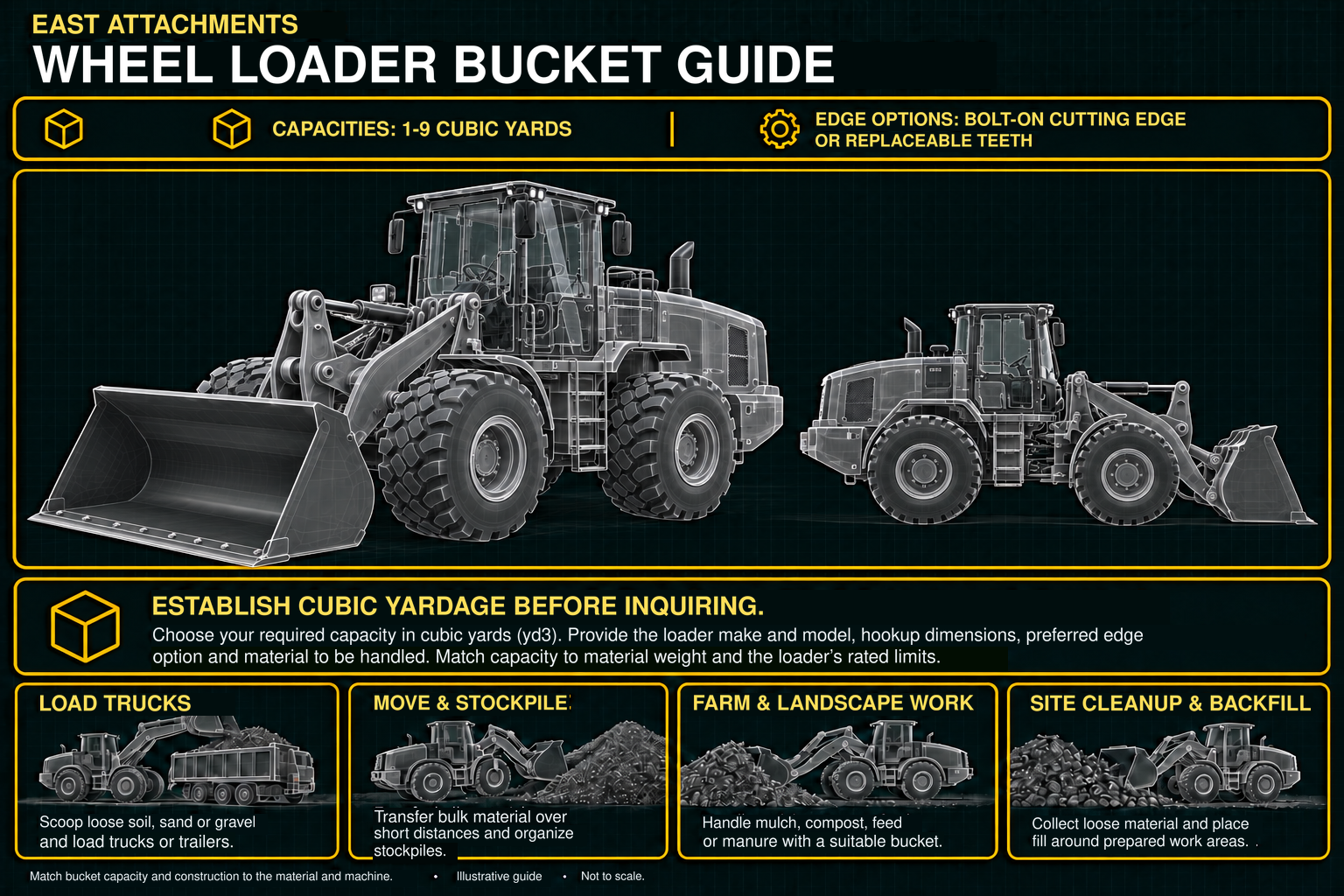
Establish the cubic yardage you need before inquiring. East Attachments offers 1–9 cubic yard loader buckets with a bolt-on cutting edge or replaceable teeth. Provide the loader make and model, hookup dimensions, preferred edge option and material to be handled; capacity must suit the material weight and loader rating.

Example sizing, not a machine-size limit. Any tonnage shown identifies the machine class used for the illustrated model and its dimensions. It does not limit the machine sizes this product can be built for. Contact East Attachments to confirm a build for your machine.

COMMON APPLICATIONS

  • Load loose soil, sand or gravel into trucks and trailers
  • Transfer bulk material over short distances and organize stockpiles
  • Handle farm and landscaping materials with a suitable bucket
  • Collect loose material and place backfill
Detailed semi-transparent CAD wheel loader bucket guide with three-quarter and side model views, 1–9 cubic yard capacities, edge options and four common uses

Wheel Loader Pin-On Rake Guide

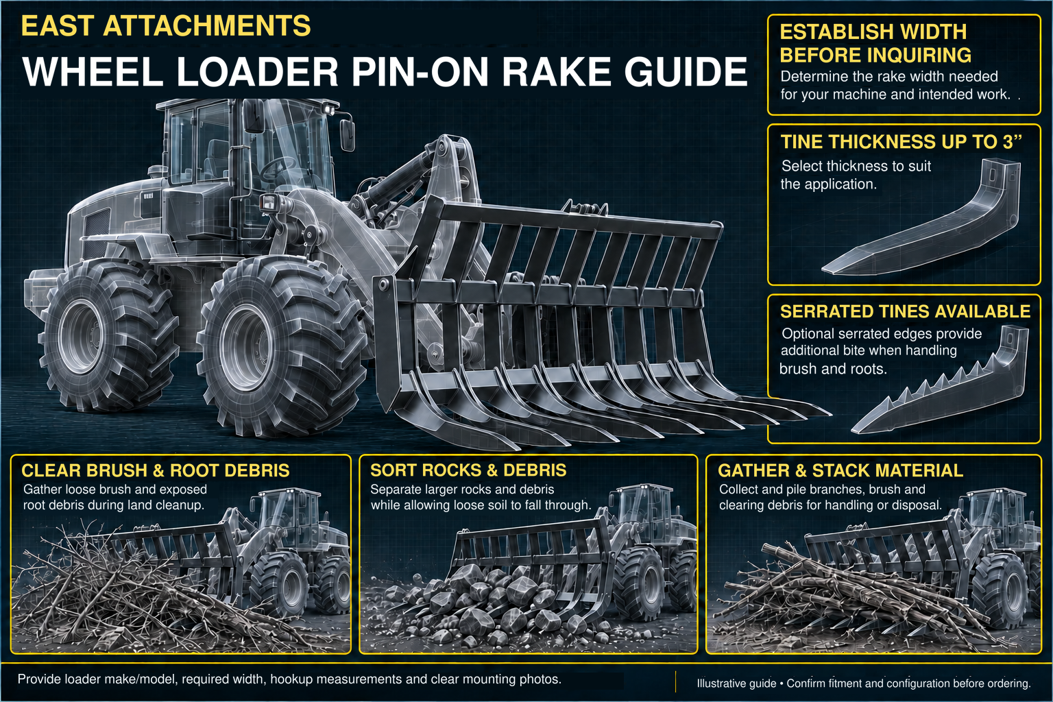
Establish the necessary rake width before inquiring. Tine thickness is available up to 3 inches, with serrated tines offered as an upgrade. Provide loader make and model, required width, hookup measurements and clear mounting photos to confirm the configuration.

Example sizing, not a machine-size limit. Any tonnage shown identifies the machine class used for the illustrated model and its dimensions. It does not limit the machine sizes this product can be built for. Contact East Attachments to confirm a build for your machine.

PRACTICAL USES

  • Gather loose brush and exposed root debris during land cleanup
  • Separate larger rocks and debris while allowing loose soil to fall through
  • Collect and pile branches, brush and clearing debris for handling or disposal
Detailed semi-transparent CAD wheel loader with pin-on rake, width selection advice, tines up to 3 inches thick, an aggressive top-edge serrated tine upgrade, and three practical rake applications

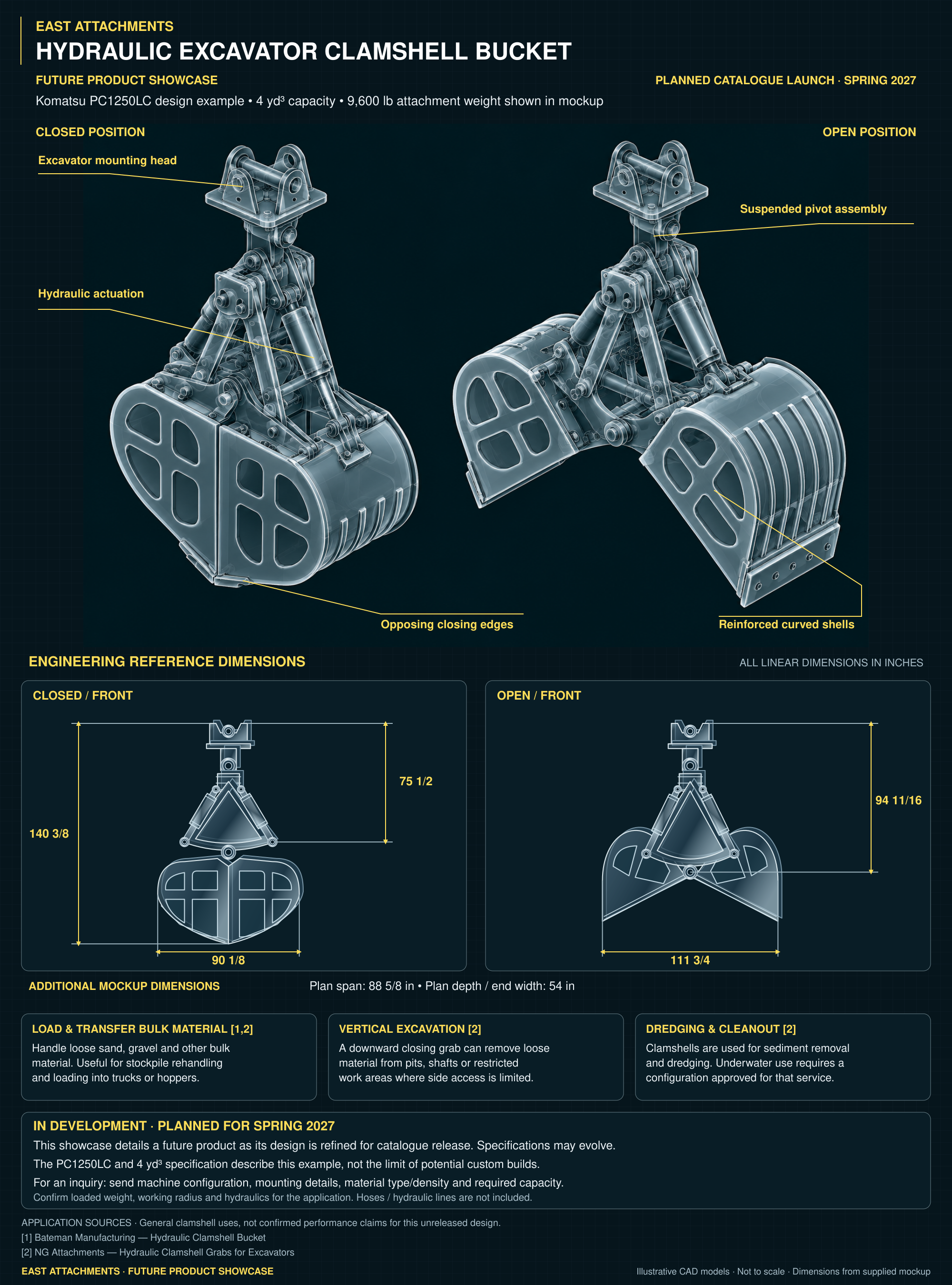
Hydraulic Excavator Clamshell Bucket — Future Product Showcase

Explore the planned hydraulic excavator clamshell bucket, targeted for catalogue release in spring 2027 as the design is refined. The supplied engineering mockup uses a Komatsu PC1250LC, 4 cubic yards of capacity and a 9,600 lb attachment weight. Dimensions describe this design example; final specifications and machine-specific fitment remain subject to confirmation.

Hydraulic hoses and hydraulic lines are not included in orders for hydraulic configurations.

Example sizing, not a machine-size limit. Any tonnage shown identifies the machine class used for the illustrated model and its dimensions. It does not limit the machine sizes this product can be built for. Contact East Attachments to confirm a build for your machine.

APPLICATIONS & INQUIRY DETAILS

  • Bulk-material loading and stockpile rehandling, including loose sand and gravel
  • Vertical excavation of loose material in pits, shafts and restricted work areas
  • Dredging and sediment cleanout with a configuration approved for underwater service
  • For an inquiry: provide machine configuration, mounting details, material type and density, required capacity and working radius

General application sources: Bateman Manufacturing and NG Attachments. These describe clamshell uses, not verified performance claims for this unreleased design.


Ghosted 3D CAD hydraulic clamshell bucket in open and closed positions, with dimensioned front views for a Komatsu PC1250LC example: 140 3/8 inch closed height, 75 1/2 inch reference height, 90 1/8 inch closed span, 94 11/16 inch open reference height and 111 3/4 inch open span; additional plan span 88 5/8 inches and depth/end width 54 inches

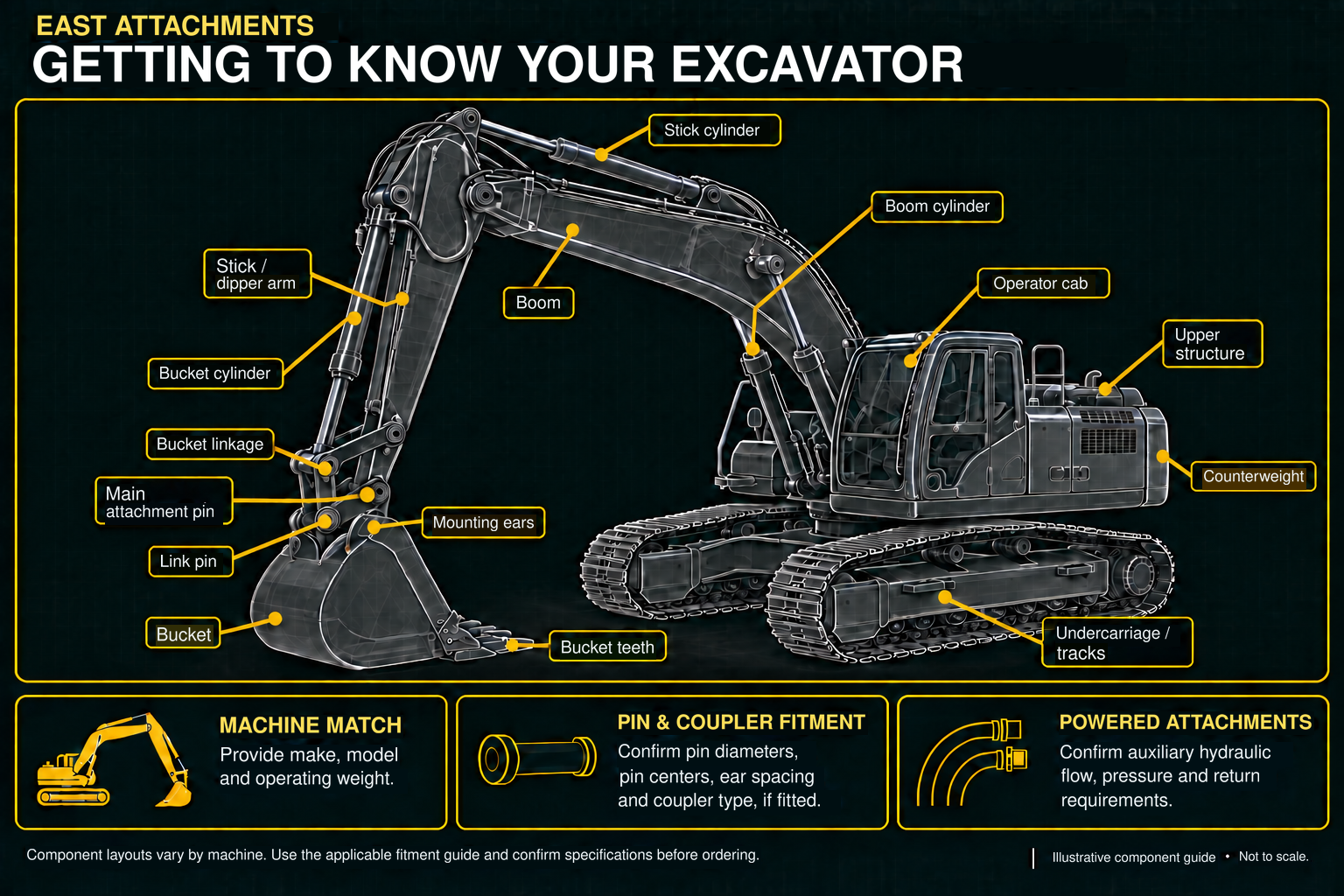
Getting to Know Your Excavator

Identify the major excavator components involved in attachment selection and use, from the boom and stick to the bucket linkage and attachment pins. Use this overview alongside the applicable measurement guide when preparing your inquiry.

Example sizing, not a machine-size limit. Any tonnage shown identifies the machine class used for the illustrated model and its dimensions. It does not limit the machine sizes this product can be built for. Contact East Attachments to confirm a build for your machine.

ATTACHMENT SELECTION BASICS

  • Machine make, model and operating weight
  • Pin diameters, pin centers, ear spacing and coupler type, if fitted
  • Auxiliary hydraulic flow, pressure and return requirements for powered attachments
Semi-transparent CAD excavator identifying boom, stick, hydraulic cylinders, bucket linkage, attachment pins, mounting ears, bucket teeth, cab, upper structure, counterweight and tracks

PRODUCT-SPECIFIC NOTES

KNOW WHAT
CHANGES.

The exact information requested depends on the attachment, mounting method and whether the excavator is using a quick coupler.

STANDARD EXCAVATOR ATTACHMENTS

Pin & Ear Geometry

Confirm inside ear width, main pin diameter, power link pin diameter and the center distance between both pins.

PIN-ON THUMBS

Extended-Length Pin Included

Complete the detailed pin-on thumb guide. The required extended-length pin is included with the pin-on thumb.

QUICK COUPLERS

Identify the Coupler

Standard and tilting quick coupler options include one set of pins. Provide the machine and product-specific dimensions requested during configuration.

TRAPEZOID BUCKETS

Confirm the Slope

Discuss a required slope with an East Attachments representative before ordering. Overall depth is based on excavator weight class.

Measurement FAQs

BEFORE THE
STEEL IS CUT.

Still uncertain about a measurement? Stop and call the shop. A confirmed dimension is more valuable than a quick estimate.

Why does East Attachments require machine measurements?

Excavator makes and models can use different pin diameters, ear widths, pin centers and coupler arrangements. Confirming the requested dimensions helps East Attachments fabricate the attachment around the actual machine instead of relying only on a model lookup.

What units should I use for pin measurements?

List every pin diameter and excavator fitment dimension in millimeters unless an East Attachments representative specifically requests another unit. Record the actual measured value rather than rounding to a nominal size.

What tools should I use to measure an excavator attachment?

Use a clean tape measure for larger distances and calipers for pin diameters, collar widths and cross holes. Remove dirt and heavy grease from the contact points before measuring, and take clear reference photos from straight-on angles.

Can East Attachments build from my machine make and model alone?

The machine make and model should always be provided, but physical measurements are still required for many attachments. If the machine uses a quick coupler, identify the coupler and follow the product-specific fitment instructions supplied by East Attachments.

When does attachment lead time begin?

The estimated lead-time period begins after East Attachments has reviewed and confirmed all required measurements. Missing, unclear or conflicting dimensions must be resolved before fabrication can be scheduled.

Are excavator attachment pins included?

Pins are sold separately for most excavator attachments. Standard and tilting quick coupler options include one set of pins, and a pin-on thumb includes the required extended-length pin.

What if I need a specific trapezoid bucket slope?

Discuss any specific slope requirement with an East Attachments representative before placing the order. Bottom width, top width and height establish the requested profile, while overall depth is based on the excavator weight class.

NEED HELP CONFIRMING A DIMENSION?

TALK TO THE SHOP.

CALL 336-829-5016 ↗CONTACT EAST ATTACHMENTS
EAST ATTACHMENTS

SEARCH THE SITE

Leave a Review